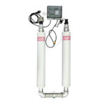
Brief Tutorial on Kalko Tronics equipped with WiFi system
Home automation today requires you to have everything under control through your own internal home network or simply via your smartphone.
Below is a guide to better check how to use Kalko Tronic WiFi systems and in the absence of it read the spies correctly on board.
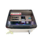
In the absence of access to the KT-WiFi some useful information on LEDs on board
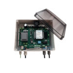
The LEDs on the card are diagnostic, the WiFi module is located on the right side.
In some older models it may not be present, but you can buy it later.
LED description (similar to all Micro / Home Series models):
DL5: (Red) Voltage presence on power channels (Vpower)
DL6: (Green/Yellow) Voltage presence 1 Microprocessor
DL7: (Arancio) Voltage presence 2 Microprocessor
DL8: (White/Blue) LAMPING Micro Processor Active
–
DL4-DL1: (BLU) Working channel presence: if the plant is on
–
DL10: (RED) Alarm presence (when it's on sounds Buzzer)
DL9: (Yellow) Active cooling fan
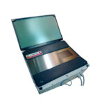
MORSETTI/CONNETTORS IN BOARD
The system has extra clamps compared to the manual.
JP3 = Forced shutdown connector (Standby): printed a G (Ground) and B (Block) on the screen.
Used in special conditions, for example it can be switched off by another Kalko Tronic (Digit) machine if necessary.
It is located next to the reset button and the flashing white led.
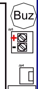
JP4 (JP5 in many plants since 2024) = Connector for cooling fan operation
The clamp can be divided into 2, a standard forced insertion connector (Jp4) and a screw clamp (pictured the orientation of + 12 Volts DC)
In case of incorrect insertion of the cables the fan will remain stationary (security against polarity reversals on fan board)
JP6 = Forced drive jumper of cooling fan.
In some models there is, for testing, the JP6, is a bridge, if it is closed: the fan will turn continuously.
You find it next to the WiFi, sometimes near the connector itself.
In the most recent models it has been eliminated, to do the test you can turn off and turn on the machine, a start of about 1 second of the fan will be done after the control of the treatment bands.
Buzzer= Sound alarm signal.
It allows the user to understand immediately when the system has a serious problem.
The buzzer has an adhesive on top of the sound dispenser that attenuates its audio, in case of noisy environments or distant areas it is possible to remove it to increase its effectiveness.
In case of pre-maintenance alarm it is possible to stop it temporarily by pressing the reset button for 5 seconds and the confirmation of acceptance of the command will take place via 2 consecutive beeps, in recent machines just pass the old R-Fid, you will have the same break as the alarm.
Jp4 (since 2024 Rfid series): a new 3-room clamp is introduced to insert a dedicated counter, available only for RFID versions.
JP7 (present on most models): This is the programming port of the system but only from 2024 with RFID models you can operate to upgrade the software of the machines by purchasing its programmer going to exploit the features that over time will be added making the machines up to date and performing.
This function can only be performed by authorised service centres.
WiFi: WiFi connection for diagnosis and online system guidance.
Sound Alarm Guide
It is also present on board the WiFi system available to the customer
1 Beep every 30 minutes
Early alarm system: the assistance is due (less than 1 month on the annual deadline)
What to do: Ensure assistance within the specified timeframe.
1 Beep every 10 seconds
Maintenance expired.
What to do: You must notify the Support Center, you can disable the alarm temporarily (7 days) by pressing the Reset button for 5 seconds.
1 Beep every 5 seconds (Home and Rfid Cap systems)
The implant may have detected a problem on the treatment bands and is warning that a check by a technician is necessary.
Continued beep alarm
The continuous alarm may intervene in some important cases:
– Burned voltage fuse
What to do: check the fuse and eventually replace it with an equivalent (see manual), notify your Support Center.
– Temperature alarm
The plant has reached a operating limit temperature
What to do: Try to keep the machine off for a short time, or create a shadow field if exposed to the sun; if the problem persists contact the Support Centre.
– Urgent maintenance
The system came into alarm before risking damage to electronics.
What to do: contact the Support Center.
– Voltage above maximum permissible (in models from 2025)
The system entered the alarm signaling the network anomaly, going to signal a voltage above 250 Vac.
What to do: contact the Service Center and turn off the machine if this alarm remains or buy a network stabilizer and connect it to KalkoTronic.
– Bands with criticality or cables disconnected
Check the bands cables and check when the last maintenance was performed, and it is important to check that there was no condensation: the latter may have ruined the treatment bands. In case of need it is recommended to create an extra cover on the hydraulic part in order to reduce the condensation problem.
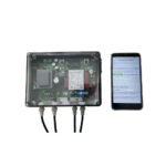
To connect to wifi there are several modes.
The first is the direct default connection in each Kalko Tronic, searching for available wifi connections you will find the SSID:
KT-DIRECT-Axxx – Default password : kt123456
The connection is customized according to the serial number of the device.
There are 2 connection modes for access to the instructions.
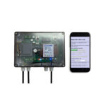
1st METHOD: DIRECT CLIENT CONNECTION
This is the connection just indicated and once connected with your smartphone you can access the system page by typing the following address bar:
192.168.1.200
Access the KalkoTronic information page
2nd METHOD: CONNECTION TO THE HOUSE NETWORK
You have to turn off the Kalko Tronic system, press the reset button and turn on the system by holding it down for about 10 seconds.
Kalko Tronic after about 10 seconds will turn on the 4 blue power leds and emit beeps, after which it should flash 1 time also the WiFi module.
In the next generation plants from 2025 onwards the check will be performed and then the 10 seconds to display of the WiFi reset procedure will be counted.
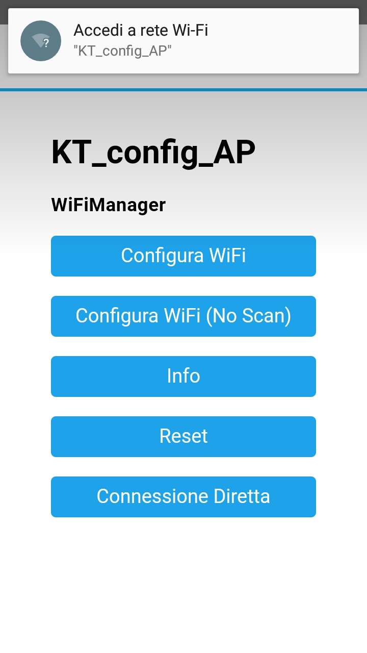
At this point you will find on your smartphone the request for configuration with an SSID called
KT_config_AP
You may ask for the password, if you request it enter that standard kt123456
In this case, configure your SSID according to the configuration manual.
By accessing your PC you will have to put the internet address set for yours. Kalko Tronic, by default it is 192.168.1.200 but you can change it.
Download Instructions
You can download the additional instruction file for KT Micro Plus WiFi here for models up to serial A 267:
INSTRUCTIONS OF REGULATION KT MICRO PLUS-WiFi INSTRUCTIONS OF REGULATION KT MICRO PLUS-WiFi
You can download the additional instruction file for KT Micro Plus/Plus Power/Hyper WiFi here for the next models.
Although systems evolved over time we have maintained the main operational features.
You will find some differences for adding new features but the connection and consultation operations are the same:
INSTRUCTIONS OF REGULATION KT MICRO PLUS-WiFi 1.2 INSTRUCTIONS OF REGULATION KT MICRO PLUS-WiFi 1.2
In case of difficulties, the technical office is available.